WedgCor Steel Buildings Maunfacturer in North Dakota
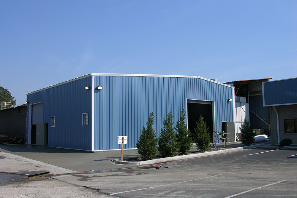
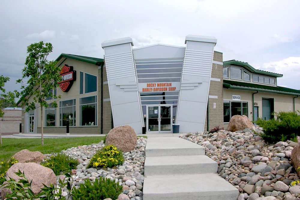
WedgCor Steel Buildings is a metal building manufacturing plant, purchased in 1974. The acquisition of the WedgCor factory, based in Jamestown, ND, was the inception of and opened the doors for Sunward Steel Buildings to become one of the most well-known, quality steel building manufacturers in the US.
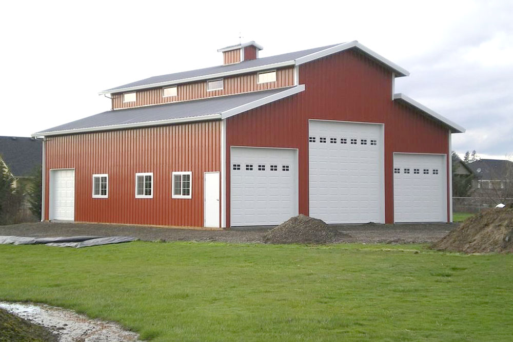
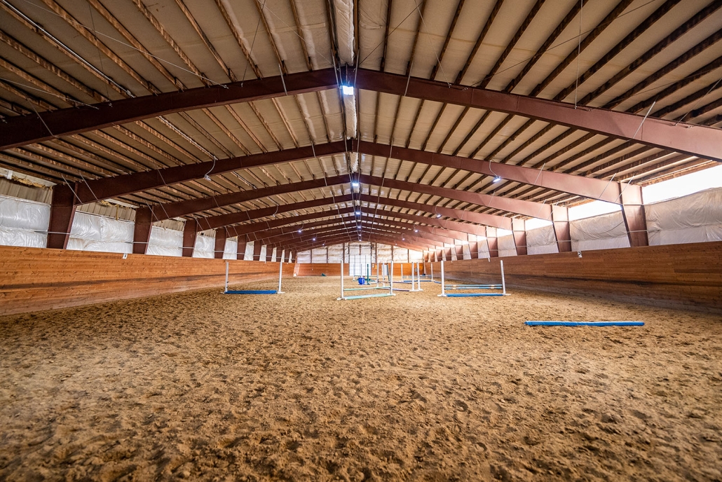
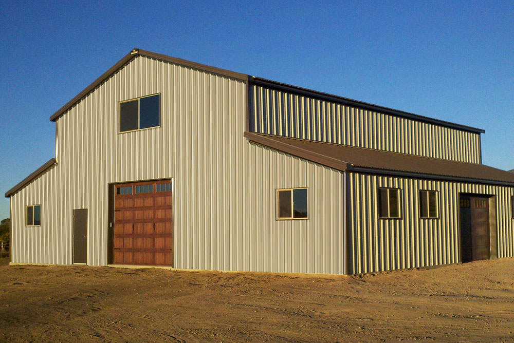
With grassroots in the agricultural industry; and with its convenient geographical location, WedgCor Steel Buildings began providing agricultural straight wall and arch style buildings throughout the Western United States. Managing the materials, building designs and delivery logistics in house gave WedgCor full control over the products being sold. Sunward quickly expanded by moving it’s company headquarters to Denver, while keeping the manufacturing operations at the Jamestown, WedgCor factory. As the family-based company grew, so did the markets’ demand for varying types of buildings, leading to Sunward Steel Buildings manufacturing and supplying a full complement of steel building types.
Premium Products
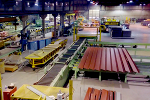
While the companies’ headquarters migrated south to Denver, the 400,000 square foot factory remained fully operational and has been a staple of the Jamestown community ever since. Innovative technology and advancements in computerized engineering allows WedgCor’s pre-fabricated steel building kits to be quickly and expertly manufactured to the industry’s highest standards. The long-tenured employees of WedgCor understand the importance of quality, which results in a very focused and purposeful attention to detail to manufacturing steel products.
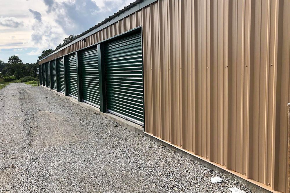
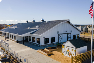
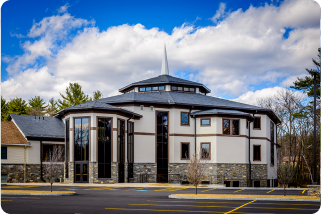
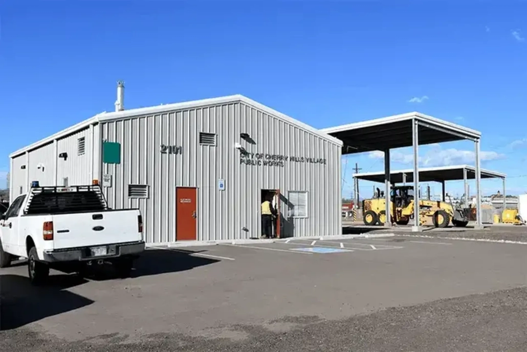
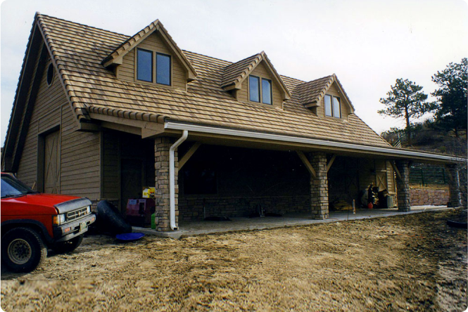
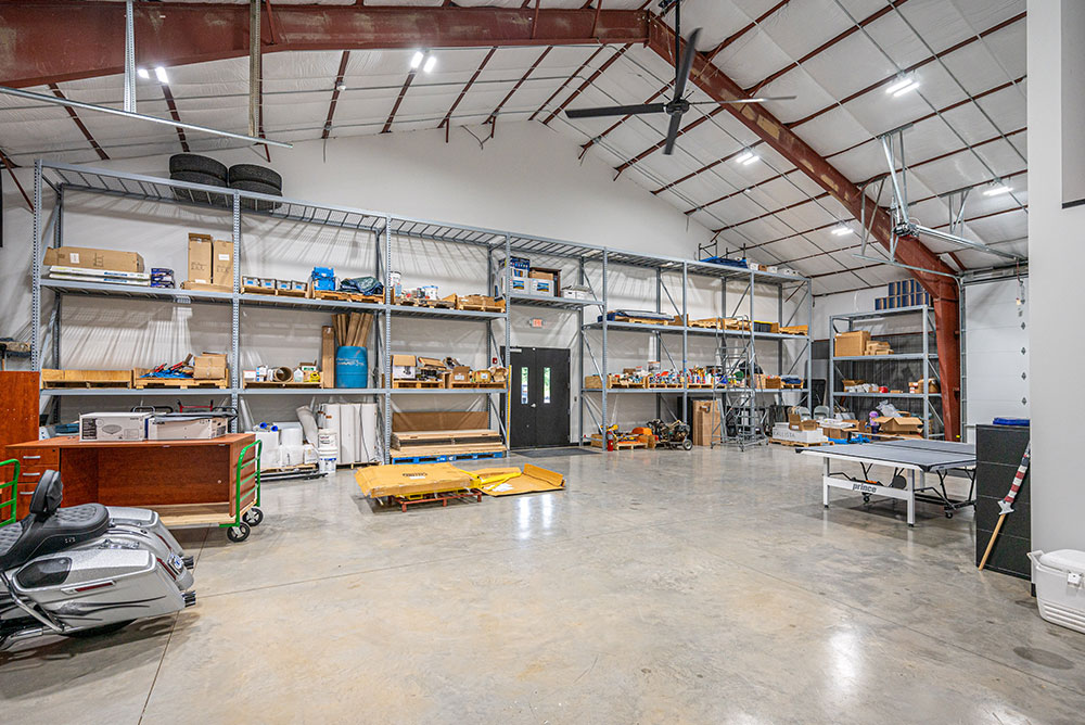
We offer cost-effective pricing for each of our steel building kits including garages, workshops, storage facilities and more. WedgCor is dedicated to delivering the best possible buying experience though our competitive pricing and excellent customer service.
Values & Integrity
Meaningful relationships are at the forefront of our business model. It is the personal and long-lasting partnerships for over 40 years that have kept WedCor and Sunward thriving. With a focus on consistent and professional care for our customers and their steel building dreams, we continue to expand. As a result, we continue to manufacture the affordable, yet superior steel buildings with the utmost honesty and integrity.
WedgCor’s Affiliate Companies
While Sunward’s Western factory, Wedgcor is located and remains in Jamestown, ND, our Eastern factory, Rockford is located in Walterboro, SC.
Learn About WedgCor’s Factory and Our Affiliated Companies
"*" indicates required fields